Thursday, September 5, 2013

Electrical codes

Electrical codes are sets of rules established by governing bodies which state:


• Type of equipment to be used in a given situation

• Appropriate use

• Installation procedures,

including how and where it should be installed

Codes usually carry mandatory compliance, and can apply nationally or to a

more limited area, such as a single local municipality. In any case, such codes can

be used to facilitate the successful installation of equipment, or stop it dead in its

tracks. Codes are powerful, and there must be a keen awareness of the various

codes and their applications.

One of the best known set of codes is the NEC (National Electrical Code), which

works in conjunction with UL requirements. The NEC is a set of electrical installation

standards published by the National Fire Protection Agency (NFPA). The

NEC is the most widely adopted electrical code in the United States and regulates

all electrical equipment used in power distribution systems, from the source to private

residences, and even to the configuration of the circuits within homes.

As you learn about different types of electrical equipment, you will become very

aware of the standards and codes that are most relevant to that particular type of

equipment. For now, just be aware of their existence and importance.

Here is a list of the most common standards and codes (but it is far from all-inclusive):


• ANSI (American National Standards Institute)

• BSI (British Standards Association)

• CE Mark (Certified European Mark)

• CEC (Canadian Electric Code)

• CSA (Canadian Standards Association)

• IEC (International Electrotechnical Commission)

• IEEE (Institute of Electrical and Electronic Engineers)

• ISO (International Standards Organization)

• NEC (National Electrical Code)

• NEMA (National Electrical Manufacturers Association)

• UL (Underwriters Laboratories, Inc.)


EATON

The new IEC 61439: better or worse than its predecessor 60439?

Improvements in IEC 61439 series compared to IEC 60439 series.

The new document structure:

Readability of the IEC 61439 has been improved compared to the IEC 60439 by implementing the

new structure of the clauses:

a) Clauses for normative reference and definitions are separated;

b) Newly introduced in clause 4 is a table with all the typical units for LV systems;

c) Also n important change is the separation the constructional requirements (clause 8) and the

performance (electrical) requirements (clause 9);

d) Design verification in clause 10 has been detailed, with more guidance and rules for the

various verification methods;

e) Routine verification in clause 11 has been separated from the design verification.

These improvements acknowledge that the assembly manufacturer/designer focuses on the

constructional and performance requirements and less bothers with de design verification which is for

the laboratories to address.


Introduction of designated design verification methods

A significant change in the new LV Assembly standard is the introduction of three methods of design

verification to replace TTA and PTTA (Type Tested Assembly and Partially Type Tested Assembly).

Where TTA in principle required complete testing of all assemblies or modular LV assembly systems,

the new standard acknowledges that assemblies or modular LV assembly systems may be

manufactured in various similar arrangements that can be sorted in variants. IEC 61439 requires

design verification of the critical variants only. To sort the critical variants a number of rules are

provided in order to avoid superfluous testing.

Where PTTA allowed calculation (that was applied to the discretion of the assembly manufacturer) for

some verifications the new standard introduces concrete rules for this method. In essence these rules

limit the loading of parts and conductors to values that are considered safe in case no true test is

performed. Note that verification of temperature rise is limited to assemblies with a total current of

1600 A, above that one is obliged to test with current.

The new standard allows the manufacturer to combine the different methods for verification as long as

it is indicated in the test report which method was used for the individual design verification.

Better or worse?

In general the new standard is better, due to the new structure, the new introduced clear methods of

verification and abandoning the vague terms TTA and PTTA.

It is worse where it bothers laboratories to verify the constructional requirements regarding the

incorporation of switching devices and components, wiring and terminals, information that is not

always easy to come by. Probably only half of the verifications in this area are useful. Many of the

items are subject to an agreement between user and manufacturer and therefore may vary for each

one-off assembly.


Written for Eaton MCC Forum

Bas Bouman

Applications and Standards LV Systems

Eaton Electric B.V.

Hengelo The Netherlands.

12 May 2010

Tuesday, September 3, 2013

Friday, August 30, 2013

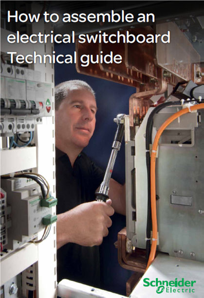
Schneider Electric - Low voltage switchboards Quality inspection guide


1. Introduction to quality inspection

1.1. Justification for quality inspection 4

1.2. Quality inspection function 5

1.3. Quality inspection responsibility 5

1.4. Quality inspector’s profile 5

1.5. Necessary documents 5

1.6. Required human resources 5

1.7. Inspection diagram 6

2. Incoming delivery inspection

2.1. Justification for the incoming inspection 8

2.2. Procedures 9

3. In-process inspection

3.1. Inspection during manufacturing 10

3.2. Justification for the inspection

during the manufacturing stage 10

3.3. Process 11

3.4. Means 11

4. Final inspection

4.1. Final inspection process 12

4.2. Operating rules 13

4.3. Non-conformity treatment process 14

4.4. Conformity declaration 15

5. Summary of tasks after final inspection stage

5.1. Customer acceptance before installation 16

5.2. Installation 16

5.3. Commissioning 16


DOWNLOAD :


http://www2.schneider-electric.com/documents/panelbuilders/en/shared/project-management/DESWED101005EN-web.pdf

Wednesday, August 28, 2013

IK Shock-Protection Rate

IK Shock-Protection Rate

IK-Class 

IK 00 No Shock-Protection 

IK 01 Resistance against impacts with an energy up to 0,150 J

IK 02 Resistance against impacts with an energy up to 0,200 J

IK 03 Resistance against impacts with an energy up to 0,350 J

IK 04 Resistance against impacts with an energy up to 0,500 J

IK 05 Resistance against impacts with an energy up to 0,700 J

IK 06 Resistance against impacts with an energy up to 1,00 J

IK 07 Resistance against impacts with an energy up to 2,00 J

IK 08 Resistance against impacts with an energy up to 5,00 J

IK 09 Resistance against impacts with an energy up to 10,00 J

IK 10 Resistance against impacts with an energy up to 20,00 J

Thursday, August 22, 2013

Friday, August 16, 2013

Thursday, August 15, 2013

Overview of the main verification changes (IEC 61439 vs IEC 60439)

> Design verification


·         Increased requirements for insulating materials and transient overvoltages withstand tests.

·         Temperature rise verification:

ü  Verification by test of each functional unit loaded alone with its rated current

ü  Clear methods for the selection of representative samples of an Assembly system to be tested

ü  Test done in 4 steps: individual functional units, main and distribution busbars, and complete

Assembly

ü  Heating resistors only allowed to simulate circuits adjacent to a circuit under test

ü  Possible verification by comparison with a tested design under strict conditions, including derating

ü  Exemption of test (calculation) only allowed up to 1600 A instead of 3150 A under strict conditions,

including a 20% derating.

·         Possible short-cricuit withstand verification by comparison with a tested design under strict

condition

·         200 operating cycles instead of 50 for locking, interlocking and withdrawable parts

·         Lifting test (from IEC 62208)

·         Corrosion resistance test for metallic parts (from IEC 62208).


> Routine verification


ü  More detailed list of the verifications

ü  More severe requirements for clearances

SCHNEIDER ELECTRIC

Wednesday, August 14, 2013

Tuesday, August 13, 2013