Tuesday, July 30, 2013
Friday, July 19, 2013
Seismic effects on enclosures
Seismic effects on enclosures
In areas where seismic activity is possible, enclosures have to withstand
more influences and material-stress than in zones with no or a minimum
seismic risk. During an earthquake, sensitive electric/electronic equipment
can be subjected to motions that can over-stress equipment framework,
whereas the amount of motions and resulting stress depends on several
factors, like:
• Structural characteristics of the building
• Framework in which the equipment is contained
• Severity of the earthquake
Therefore, it is important to use enclosures that have been tested for
specific seismic zones.
Seismic certification
If compliance with the UBC-Zone certification is required, the requirements
for conformity are stated in GR-63-CORE ‘NEBS Requirements: Physical
Protection (NEBS or Network Equipment-Building System). This standard
identifies the minimum generic compatibility criteria for telecommunications
equipment, especially for:
• Earthquake and Office Vibration (Zone requirements)
• Fire resistance
• Thermal robustness
• Transportation and Handling
• Acoustic Noise
• Airborne Contaminates
The testing criteria of the GR-63-CORE are as follows:
• Door does not open during test.
• Equipment still operable immediately before and after test.
• Enclosure must be base mountable.
• Enclosure is bolted down to concentrate slab.
To test for physical performance, the GR-63-CORE contains some different
physical performance criteria and certification levels, such as:
• R4-44: All equipment shall be constructed to sustain the waveform
testing without permanent structural or mechanical damage.
• R4-45: Maximum single amplitude deflection at top of enclosure
relative to the base does not exceed 75mm (3”).
• R4-46: System should have a natural mechanical frequency greater
than 2.0Hz as determined by swept sine survey.
RITTAL
Tuesday, July 16, 2013

Saturday, July 13, 2013
Residual-current device RCD
A residual-current device (RCD), or residual-current circuit breaker (RCCB) or residual twin-direct current couplet (R2D2), is an electrical wiring device that disconnects a circuit whenever it detects that the electric current is not balanced between the energized conductor and the return neutral conductor. Such an imbalance may indicate current leakage through the body of a person who is grounded and accidentally touching the energized part of the circuit. A lethal shock can result from these conditions. RCCBs are designed to disconnect quickly enough to prevent injury caused by such shocks. They are not intended to provide protection against overcurrent (overload) or short-circuit conditions.

Tuesday, July 9, 2013
Sizing of protective earthing conductor
Below is based on IEC 60364-5-54. This table provides two methods of determining the appropriate c.s.a. for both PE or PEN conductors.
| c.s.a. of phase | Minimum c.s.a. of | Minimum c.s.a. of | ||
| Cu AI | ||||
| Simplified | Sph≤ 16 | Sph(2) | Sph(3) | Sph(3) |
| 16 < Sph ≤ 25 | 16 | 16 | ||
| 25 < Sph ≤ 35 | 25 | |||
| 35 < Sph ≤ 50 | Sph/2 | Sph/2 | ||
| Sph > 50 | Sph/2 | |||
| Adiabatic method | Any size |
| ||

(1) Data valid if the prospective conductor is of the same material as the line conductor. Otherwise, a correction factor must be applied.
(2) When the PE conductor is separated from the circuit phase conductors, the following minimum values must be respected:
§ 2.5 mm2 if the PE is mechanically protected
§ 4 mm2 if the PE is not mechanically protected
(3) For mechanical reasons, a PEN conductor, shall have a cross-sectional area not less than 10 mm2 in copper or 16 mm2 in aluminium.
(4) Refer to table G53 for the application of this formula.
Wikipedia
Monday, July 8, 2013


Panel board types

SIEMENS
Commercial and Industrial Power distribution systems
Power distribution systems used in multi-family, commercial, and industrial facilities are more complex. A power distribution system consists of metering devices to measure power consumption, main and branch disconnects, protective devices, switching devices to start and stop power flow, conductors, and transformers. Power may be distributed through various switchboards, transformers, and panel boards.
Good distribution systems don’t just happen. Careful engineering is required so that the distribution system safely and efficiently supplies adequate electric service to existing loads and has expansion capacity for possible future loads.
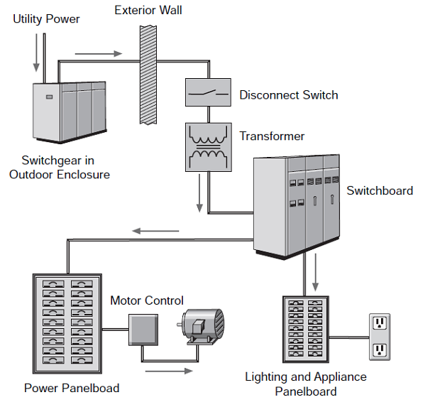
- siemens
Friday, July 5, 2013

Thursday, July 4, 2013
Busbars And Their Uses
Used in electrical power distribution, busbars are usually made out of aluminium or copper and they are able to conduct electricity to transmit power from the source of electric power to the load. They are usually supported by insulators and conduct electricity within switchboards, substations or other electric apparatus. Some typical applications of these devices can be to form the interconnectedness of the incoming and outgoing electrical transmission lines and transformers at an electrical substation; supplying huge amounts of amperes to the electrolytic process in an aluminium smelter by using large busbars and also interconnecting generators to the main transformers in a power plant.
The size of the busbar determines its application and the amount of current that it can carry safely. They can be tubular, solid or flat depending on the application and to serve different needs. A tubular busbar is hollow and this shape allows it to dissipate heat more efficiently as it has a high surface area. Hollow or flat shaped bus bars are prevalent in high current applications. Also, the hollow section of a busbar is generally stiffer as compared to a solid rod, thus this allows a greater span between busbar support in outdoor switchyards. The smallest cross-sectional area of a busbar can be as little as 10mm2, but electrical substations would make use of busbars with a diameter of more than 50 mm as they carry great amounts of amperes. Aluminium smelters would make use of these large busbars to carry tens of thousands of amperes to the electrochemical cells that produce aluminium from molten salts.
As they carry large amount of electricity, it is important to support the busbars with insulation to prevent any accidents from happening whereby someone may accidentally touch the bus bar. Insulation can either support the busbar or completely surround it. They can be prevented from accidental touch by placing the bus bars at an elevated height so it would not be easily accessible or by a metal earth enclosure. Some bus bars such as the earth bus bar can be bolted directly into the housing chassis of their enclosure. This prevents unwanted touch and also saves the bus bar from any damage it may incur when left exposed. There are several other ways that busbars can be connected to one another or the electrical apparatus with which they would be used with such as by bolting, clamping or welding connections. Switchgears, panelboards or busways usually contain the busbars and the electrical supply is split by the distribution boards into different circuits. Busways are a type of busbars that have a protective cover and are long in shape. Also referred to as bus ducts, these devices allow the electricity to branch out to different circuits at any point along its surface; unlike regular busbars that allow branching of the main supply only at one location.
The most common types of busbars present in the industry today are rigid busbars, strain busbars and insulated phase busbars. Each of these different types of busbars has different applications and uses. The rigid busbars are used in low, medium or high voltage applications, constructed with aluminium or copper bars and they make use of porcelain to insulate them. As for the strain busbars, they are mostly used in high voltage applications and are usually strung between the metal structures of a substation. They are held in place by suspension-type insulators. Lastly, as for the insulated-phase bus bars, they are used at medium voltage and similar to the rigid bus bars, they are rigid bars that are supported by insulators. These busbars are able to eliminate short circuits between adjacent phases.
Monday, July 1, 2013
Enclosure Design for EMC
Most equipment manufactures choose to design custom housings for their electronics products
in order to differentiate them in the market place. Usually enclosure design is driven by the two
beasts of beauty and cost, with EMC requirements an irritating afterthought.
The ideal enclosure from an EMC point of view is the perfect Faraday cage. Take the PCBs
that make up a typical product, wrap them in a seamless monolith of copper without apertures
and bingo! You’ve fixed it. Unfortunately this solution is impractical.
The art of good enclosure design is therefore to get “as close as is necessary” to the Faraday
cage, without sacrificing the aesthetic appeal of the product or significantly increasing its cost.
For most designers “As close as is necessary” is usually defined as meeting standard or type
specific requirements. This usually involves at least:
(i) Containing Radiated Emissions
(ii) Providing Radiated Immunity
(iii) Providing ESD Immunity
(iv) Providing Fast Transient Immunity
In designing a compliant enclosure the designer needs to look at the following:
(i) Mechanical components - their material composition and coatings
(ii) Electrically bonding the enclosure components
(iii) Electrically bonding the internal hardware and its interfaces to the enclosure
(iv) Dealing with apertures in the enclosure
(v) Screening and partitioning inside the enclosure
(vi) Earthing the product
Component Material and Coatings
Generally the enclosure designer will work with components made from folded steel or
aluminium alloy or bulk extruded alloy and possibly vacuum formed aluminium or plastic.
Where the volumes of finished product justify the tooling expense, the designer might also use
injection moulded plastic or rubber or die cast aluminium.
Often housings made entirely of conductive metal components form poor EMC
enclosures simply because the individual components have been painted or coated in a
non-conductive material.
There are however a wide range of affordable conductive coatings available. For example:
= For aluminium components - alochrome plating rather than non-conductive anodising.
= For steel components - zinc galvanising or passivated zinc plating (zinc and chromate
passivated) for corrosion resistance. Where aesthetic appeal is important - bright nickel
or chromium plating. Note: Zintec is a sheet steel with conductive zinc coating and can
be used as an alternative to plating where corrosion at the cut edges of a component is
not an issue.
= For plastic components - internal metalisation or conductive carbon coating. Partially
conductive carbon loaded plastics can be used but often the strength and flexibility of a
loaded plastic is inferior to an unloaded component.
Subscribe to:
Posts (Atom)