SIEMENS
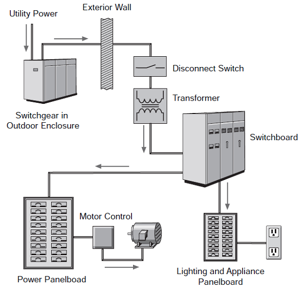
Power distribution systems used in multi-family, commercial, and industrial facilities are more complex. A power distribution system consists of metering devices to measure power consumption, main and branch disconnects, protective devices, switching devices to start and stop power flow, conductors, and transformers. Power may be distributed through various switchboards, transformers, and panel boards.
Good distribution systems don’t just happen. Careful engineering is required so that the distribution system safely and efficiently supplies adequate electric service to existing loads and has expansion capacity for possible future loads.
- siemens
Used in electrical power distribution, busbars are usually made out of aluminium or copper and they are able to conduct electricity to transmit power from the source of electric power to the load. They are usually supported by insulators and conduct electricity within switchboards, substations or other electric apparatus. Some typical applications of these devices can be to form the interconnectedness of the incoming and outgoing electrical transmission lines and transformers at an electrical substation; supplying huge amounts of amperes to the electrolytic process in an aluminium smelter by using large busbars and also interconnecting generators to the main transformers in a power plant.
The size of the busbar determines its application and the amount of current that it can carry safely. They can be tubular, solid or flat depending on the application and to serve different needs. A tubular busbar is hollow and this shape allows it to dissipate heat more efficiently as it has a high surface area. Hollow or flat shaped bus bars are prevalent in high current applications. Also, the hollow section of a busbar is generally stiffer as compared to a solid rod, thus this allows a greater span between busbar support in outdoor switchyards. The smallest cross-sectional area of a busbar can be as little as 10mm2, but electrical substations would make use of busbars with a diameter of more than 50 mm as they carry great amounts of amperes. Aluminium smelters would make use of these large busbars to carry tens of thousands of amperes to the electrochemical cells that produce aluminium from molten salts.
As they carry large amount of electricity, it is important to support the busbars with insulation to prevent any accidents from happening whereby someone may accidentally touch the bus bar. Insulation can either support the busbar or completely surround it. They can be prevented from accidental touch by placing the bus bars at an elevated height so it would not be easily accessible or by a metal earth enclosure. Some bus bars such as the earth bus bar can be bolted directly into the housing chassis of their enclosure. This prevents unwanted touch and also saves the bus bar from any damage it may incur when left exposed. There are several other ways that busbars can be connected to one another or the electrical apparatus with which they would be used with such as by bolting, clamping or welding connections. Switchgears, panelboards or busways usually contain the busbars and the electrical supply is split by the distribution boards into different circuits. Busways are a type of busbars that have a protective cover and are long in shape. Also referred to as bus ducts, these devices allow the electricity to branch out to different circuits at any point along its surface; unlike regular busbars that allow branching of the main supply only at one location.
The most common types of busbars present in the industry today are rigid busbars, strain busbars and insulated phase busbars. Each of these different types of busbars has different applications and uses. The rigid busbars are used in low, medium or high voltage applications, constructed with aluminium or copper bars and they make use of porcelain to insulate them. As for the strain busbars, they are mostly used in high voltage applications and are usually strung between the metal structures of a substation. They are held in place by suspension-type insulators. Lastly, as for the insulated-phase bus bars, they are used at medium voltage and similar to the rigid bus bars, they are rigid bars that are supported by insulators. These busbars are able to eliminate short circuits between adjacent phases.
Most equipment manufactures choose to design custom housings for their electronics products
in order to differentiate them in the market place. Usually enclosure design is driven by the two
beasts of beauty and cost, with EMC requirements an irritating afterthought.
The ideal enclosure from an EMC point of view is the perfect Faraday cage. Take the PCBs
that make up a typical product, wrap them in a seamless monolith of copper without apertures
and bingo! You’ve fixed it. Unfortunately this solution is impractical.
The art of good enclosure design is therefore to get “as close as is necessary” to the Faraday
cage, without sacrificing the aesthetic appeal of the product or significantly increasing its cost.
For most designers “As close as is necessary” is usually defined as meeting standard or type
specific requirements. This usually involves at least:
(i) Containing Radiated Emissions
(ii) Providing Radiated Immunity
(iii) Providing ESD Immunity
(iv) Providing Fast Transient Immunity
In designing a compliant enclosure the designer needs to look at the following:
(i) Mechanical components - their material composition and coatings
(ii) Electrically bonding the enclosure components
(iii) Electrically bonding the internal hardware and its interfaces to the enclosure
(iv) Dealing with apertures in the enclosure
(v) Screening and partitioning inside the enclosure
(vi) Earthing the product
Component Material and Coatings
Generally the enclosure designer will work with components made from folded steel or
aluminium alloy or bulk extruded alloy and possibly vacuum formed aluminium or plastic.
Where the volumes of finished product justify the tooling expense, the designer might also use
injection moulded plastic or rubber or die cast aluminium.
Often housings made entirely of conductive metal components form poor EMC
enclosures simply because the individual components have been painted or coated in a
non-conductive material.
There are however a wide range of affordable conductive coatings available. For example:
= For aluminium components - alochrome plating rather than non-conductive anodising.
= For steel components - zinc galvanising or passivated zinc plating (zinc and chromate
passivated) for corrosion resistance. Where aesthetic appeal is important - bright nickel
or chromium plating. Note: Zintec is a sheet steel with conductive zinc coating and can
be used as an alternative to plating where corrosion at the cut edges of a component is
not an issue.
= For plastic components - internal metalisation or conductive carbon coating. Partially
conductive carbon loaded plastics can be used but often the strength and flexibility of a
loaded plastic is inferior to an unloaded component.
Old color code

New color code:

| NEMA Rating | IP Equivalent | NEMA Definition | IP Definition | |
| 1 | IP10 | Enclosures constructed for indoor use to provide a degree of protection to personnel against incidental contact with the enclosed equipment and to provide a degree of protection against falling dirt | 1 = Protected against solid foreign objects of 50mm in diameter and greater | 0 = Not Protected |
| 2 | IP11 | Enclosures constructed for indoor used to provide a degree of protection to personnel against incidental contact with the enclosed equipment, to provide a degree of protection against falling dirt, and to provide a degree of protection against dripping and light splashing of liquids | 1 = Protected against solid foreign objects of 50mm in diameter and greater | 1 = Protected against vertically falling water drops |
| 3 | IP54 | Enclosures constructed for either indoor or outdoor used to provide a degree of protection to personnel against incidental contact with the enclosed equipment; to proved a degree of protection against falling dirt, rain, sleet, snow, and windblown dust; and that will undamaged by external formation of ice on the enclosure | 5 = Protected against dust - Limited to ingress (no harmful deposit) | 4 = Protected against water sprayed from all directions - Limited to ingress permitted. |
| 3R | IP14 | Enclosures constructed for either indoor or outdoor used to provide a degree of protection to personnel against incidental contact with the enclosed equipment; to provide a degree of protection against falling dirt, rain, sleet, and snow; and that will be undamaged by external formation of ice on the enclosure | 1 = Protected against vertically falling water drops | 4 = Protected against water sprayed from all directions - Limited to ingress permitted. |
| 3S | IP54 | Enclosures constructed for either indoor or outdoor use to provide a degree of protection to personnel against incidental contact with the enclosed equipment; to provide a degree of protection against falling dirt, rain, sleet, snow, and windblown dust; and in which the external mechanism(s) remain operable when ice laden. | 5 = Protected against dust - Limited to ingress (no harmful deposit) | 4 = Protected against water sprayed from all directions - Limited to ingress permitted. |
| 4 | IP66 | Enclosures constructed for either indoor or outdoor use to provide a degree of protection to personnel against incidental contact with the enclosed equipment; to provide a degree of protection against falling dirt, rain, sleet, snow, windblown dust, splashing water, and hose-directed water; and that will be undamaged by the external formation of ice on the enclosure | 5 = Protected against dust - Limited to ingress (no harmful deposit) | 6 = Protected against strong jets of water from all directions - Limited to ingress permitted. |
| 4X | IP66 | Enclosures constructed for either indoor or outdoor use to provide a degree of protection to personnel against incidental contact with the enclosed equipment; to provide a degree of protection against falling dirt, rain, sleet, snow, windblown dust, splashing water, hose-directed water, and corrosion; and that will be undamaged by thee external formation of ice on the enclosure | 5 = Protected against dust - Limited to ingress (no harmful deposit) | 6 = Protected against strong jets of water from all directions - Limited to ingress permitted. |
| 5 | IP52 | Enclosures constructed for indoor use to provide a degree of protection to personnel against incidental contact with the enclosed equipment; to provide a degree of protection against falling dirt; against settling airborne dust, lint, fibers, and flyings; and to provide a degree of protection against dripping and light splashing of liquids. | 5 = Protected against dust - Limited to ingress (no harmful deposit) | 2 = Protected against direct sprays of water up to 15° from the vertical. |
| 6 | IP67 | Enclosures constructed for either indoor or outdoor use to provide a degree of protection to personnel against incidental contact with the enclosed equipment; to provide a degree of protection against falling dirt; against hose-directed water and the entry of water during occasional temporary submersion at a limited depth; and that will be undamaged by the external formation of ice on the enclosure. | 6 = Totally protected against dust | 7 = Protected against the effects of temporary immersion between 15cm and 1m. Duration of test 30 minutes. |
| 6P | IP67 | Enclosures constructed for either indoor or outdoor use to provide a degree of protection to the personnel against incidental contact with the enclosed equipment; to provide a degree of protection against falling dirt; against hose-directed water and the entry of water during prolonged submersion at a limited depth; and that will be undamaged by the external formation of ice on the enclosure | 6 = Totally protected against dust | 7 = Protected against the effects of temporary immersion between 15cm and 1m. Duration of test 30 minutes. |
| 12 and 12K | IP52 | Enclosures constructed (without knockouts) for indoor use to provide a degree of protection to personnel against incidental contact with the enclosed equipment; to provide a degree of protection against falling dirt; against circulating dust, lint, fibers, and flying; and against dripping and light splashing of liquids | 5 = Protected against dust - Limited to ingress (no harmful deposit) | 2 = Protected against direct sprays of water up to 15° from the vertical. |
| 13 | IP54 | Enclosures constructed for indoor use to provide a degree of protection to personnel against incidental contact with the enclosed equipment; to provide a degree of protection against falling dirt; against circulating dust, lint, fibers, and flyings; and against the spraying, splashing, and seepage of water, oil, and noncorrosive coolants. | 5 = Protected against dust - Limited to ingress (no harmful deposit) | 4 = Protected against water sprayed from all directions - Limited to ingress permitted. |
There are several different uses of IP Codes, as described in IEC 529. IP Codes can have the following arrangement:
· First character only, such as IP 3X
· Second character only, such as IP X4
· Both characters, such as IP 34
The first character indicates the degree of protection against the ingress of solid foreign objects. First character definitions are as follows:
0 - Non-protected
1 - Protected against solid foreign objects of 50 mm diameter and greater
2 - Protected against solid foreign objects of 12.5 mm diameter and greater
3 - Protected against solid foreign objects of 2.5 mm diameter and greater
4 - Protected against solid foreign objects of 1.0 mm diameter and greater
5 - Dust-protected
6 - Dust-tight
The second character of the IP Code indicates the degree of protection against the ingress of water with harmful effects. Second-character definitions are as follows:
0 - Non-protected
1 - Protected against vertically falling water drops
2 - Protected against vertically falling water drops as the enclosure is tilted 15 degrees
3 - Protected against spraying water
4 - Protected against splashing water
5 - Protected against water jetting
6 - Protected against powerful water jetting
7 - Protected against temporary immersion
8 - Protected against continuous immersion
UL sample requirements
Some UL testing chambers are limited in size. Please note that these size restrictions apply only for the tests specified below. If your sample will not fit into the test chambers, a smaller prototype may be used as long as the same type of hinges, gaskets, and other mechanisms are used at the same pressures.
· IP 5X/6X -- Sample must fit into dust chamber measuring 3-1/2 ft. wide by 3 ft. tall by 7 ft. long. The door to the chamber measures 2 ft. by 3-1/2 ft.
· IP X7/X8 -- Sample must fit into container measuring 23 in. diameter by 6 ft. deep.
| Industrial Control Equipment is a term commonly used to represent discrete components ranging from selector switches, relays, contactors, motor starters, timers, pilot lights, to complex system of these components. It encompasses more than 30 different product categories and 100 different devices (See Figure1). |
| Figure 1: Examples of industrial control devices covered by UL 508 | |
| Industrial Control Devices | Examples |
| Motor starters and controllers | Including manual, magnetic, and solid-state starters and controllers |
| Overload relays | Including thermal, magnetic, and solid-state overload relays |
| Control circuit switches and relays | Including pushbutton stations, selector switches, time-delay relays and pilot lights |
| Switches | Including float, flow, pressure, vacuum-operated, mercury-tube and proximity switches |
| Autotransformers, resistors and rheostats | Variable voltage and motor starting |
| Programmable controllers | Including numerical control systems and industrial microprocessor/computer systems |
| Industrial Control Equipment is used extensively in industrial applications including starting, stopping, regulating, controlling, reversing, changing speed, or protecting electric motors. Components for motor control are installed primarily in control panels, motor control centers, industrial machines as well as energy distribution assemblies. Industrial Control Equipment is required to be designed, built and evaluated for their function and safety in compliance with an established National / International standard. UL 508, covers the safety requirements for Industrial Control Equipment. |
Overload relay with reclosing lockout
They should always be used where
continuous contact devices (two-wire
control) are concerned (e.g. pressure and
position switches), to prevent automatic
restarting. The reset button can be fitted as
an external feature in order to make it
accessible to all personnel. Overload
relays for example are always supplied
with manual reset. but can be converted to
automatic reset by the user.
Overload relays without reclosing
lockout
They can be used only with pulsed contact
devices (three-wire control) such as
pushbuttons etc., because on these, the
cooling of the bimetal strips cannot lead to
automatic reconnection.
Special circuitry
Special circuitry such as is found in
star-delta switches, individually
compensated motors, current
transformer-operated overload relays etc.
may require that the relay settings deviates
from the motor rated operational current.
Frequently recurring operating cycles
It makes motor protection difficult. The
relay should be set to higher than rated
motor current in view of its shorter time
constant. Motors which are rated for a high
operating frequency will stand this setting
to a certain degree. Although this will not
ensure complete protection against
overload, it will nevertheless provide
adequate protection against non-starting.
Back-up fuses and instantaneous
releases
They are needed to protect not only the
motor, but also the relay, against the
effects of short-circuits. Their maximum
rating is shown clearly on every relay and
must be adhered to without fail. Higher
ratings – chosen for instance according to
the cable cross-section – would lead to the
destruction of the motor and relay.
The following important questions and
answers give a further guide to the
behaviour of an installation with motor
protection.
To what current must the overload relay
properly be set?
To the rated motor current – no higher, no
lower. A relay set to too low a figure will
prevent the full utilization of the motor; set
too high, it will not guarantee full overload
protection. If a correctly set relay trips too
frequently, then either the load on the
motor should be reduced or the motor
should be exchanged for a larger one.
When is it right for the overload relay to
trip?
Only when the current consumption of the
motor increases due to mechanical
overloading of the motor, undervoltage or
phase failure when the motor is under full
load or thereabout, or when the motor fails
to start due to a stalled rotor.
When does the overload relay fail to trip
in good time although the motor is
endangered?
With changes in the motor which do not
cause an increase in current consumption:
Effects of humidity, reduced cooling due to
a reduction in speed or motor dirt,
temporary additional external heating of
the motor or bearing wear.

What causes destruction of the overload
relay?
Destruction will take place only in the
event of a short-circuit on the load side of
the relay when the back-up fuse is rated
too high. In most cases, this will also
endanger the contactor and motor.
Therefore, always adhere to the maximum
fuse rating specified on every relay.
3-pole overload relays should be so
connected in the case of single-phase and
DC motors so that all three poles of the
overload relay carry the current, whether
in 1-pole or 2-pole circuits.
An important characteristic feature of
overload relays conforming to IEC/EN
60947-4-1 are the tripping classes (CLASS
10 A, 10, 20, 30). They determine different
tripping characteristics for the various
starting conditions of motors (normal
starting to heavy starting duty).
EATON